Lead-free solders are a group of joining alloys formulated without intentionally added lead. This article covers tin-based compositions containing copper, silver or both. They are used in electronics, electrical engineering and other applications that require joining below the melting temperature of the components themselves.
What are lead-free solders?
During soldering, the filler alloy melts while the components remain solid. The liquid solder wets prepared surfaces and forms a joint upon cooling. Intermetallic layers may develop at the interface with the base metal.
The notation Sn + Cu/Ag groups together the Sn–Cu, Sn–Ag and Sn–Ag–Cu systems. It does not mean that every grade contains all three elements. The Sn–Ag–Cu family is commonly abbreviated to SAC.
A lead-free composition does not necessarily contain absolutely zero lead: permitted trace impurities are defined by the specification. Other lead-free systems contain bismuth, indium and additional elements.
Chemical composition
| Element | Symbol | Role in the alloy |
|---|---|---|
| Tin | Sn | Base metal of the solders discussed, providing the basis for joint formation |
| Copper | Cu | Influences microstructure and interaction with copper surfaces |
| Silver | Ag | Forms microstructural constituents affecting mechanical properties and thermal cycling behaviour |
| Additional elements | Ni, Ge and others | Used in small amounts in certain grades to modify microstructure and processing characteristics |
Element percentages, purity and impurity limits must be checked against the documentation for the specific solder. Materials sharing the same basic alloy system can differ significantly in performance.
Physical and processing properties
- Appearance: silvery-grey; joint surfaces may be shiny or matt.
- Melting: approximately 217–227 °C for the compositions listed below; other lead-free systems can differ substantially.
- Wetting: depends on alloy composition, flux, component finish and thermal conditions.
- Conductivity: provides electrical contact but does not replace joint cross-section and resistance calculations.
- Mechanical behaviour: depends on microstructure, joint geometry and loading conditions.
- Service life: affected by thermal cycling, creep and intermetallic layer growth.
Common compositions
| Designation | Composition by mass | Approximate melting temperature | Characteristics |
|---|---|---|---|
| Sn99.3Cu0.7 | 99.3% Sn; 0.7% Cu | 227 °C | Silver-free composition used, among other applications, for wave soldering |
| Sn96.5Ag3.5 | 96.5% Sn; 3.5% Ag | 221 °C | Eutectic tin-silver solder |
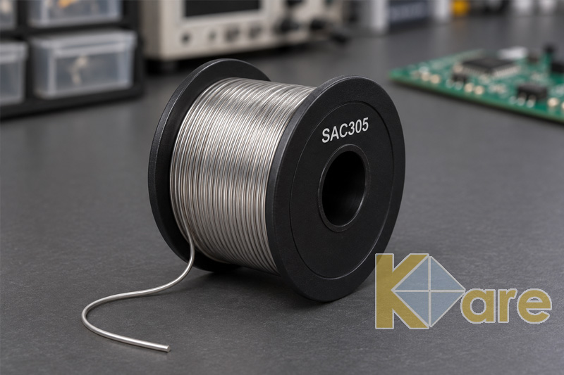
| SAC305 | 96.5% Sn; 3.0% Ag; 0.5% Cu | 217–220 °C | Widely used electronics assembly alloy |
The melting point or range is an alloy characteristic, not a ready-made soldering iron or oven setting. The process profile must reflect the material documentation, assembly thermal mass and component temperature limits.
Product forms
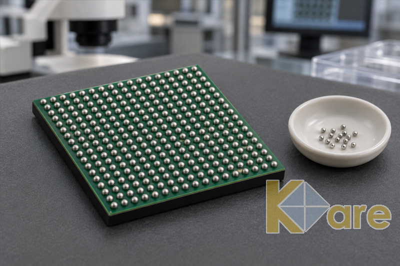
Lead-free solders are supplied as wire, rods, bars, powders, spheres and shaped preforms. Wire may be solid or contain a flux core.
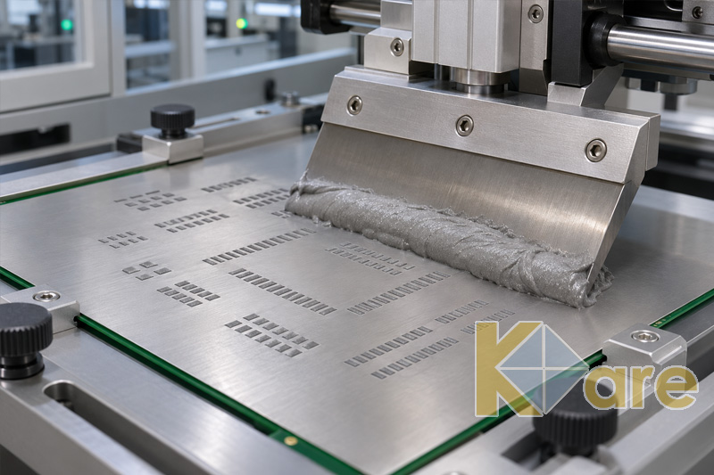
Solder paste is a mixture of solder powder and a flux formulation. It is not a separate metallic alloy grade: a composition such as SAC305 can be supplied in several product forms.
Soldering and joint quality
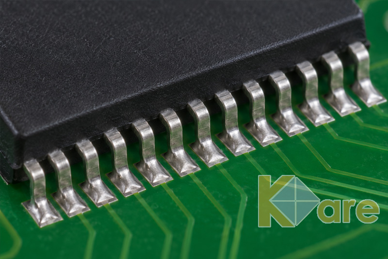
Successful soldering requires compatible surfaces, a suitable flux and adequate heating of the joint area. Paste reflow, wave soldering, selective soldering and hand soldering need different process conditions and material delivery forms.
Excessive temperature or prolonged heating can damage components and alter joint microstructure. A matt lead-free joint surface does not by itself indicate a defect: wetting, shape, fill and other quality criteria must be assessed.
Applications
- Surface-mount assembly: solder pastes for connecting components to printed circuit board pads.
- Through-hole assembly: wave and selective soldering of leaded components.
- Manual assembly and repair: solder wire of a suitable grade and diameter.
- Electronic packaging: spheres and preforms for specific interconnection designs.
- Technical joints: selected electrical and pipework assemblies where the material has the required approval.
Electronics solder must not automatically be considered suitable for drinking-water systems or other specialised uses. The intended application of the alloy, flux and finished product must be verified.
Differences from tin-lead solders
| Characteristic | Lead-free solders discussed | Sn63Pb37 |
|---|---|---|
| Basic composition | Tin with copper and/or silver | 63% tin and 37% lead |
| Melting | Approximately 217–227 °C for the listed grades | 183 °C |
| Thermal conditions | Usually require a higher process temperature | Usually lower for a comparable application |
| Material substitution | Requires process and reliability validation | Not a direct equivalent of SAC or Sn–Cu |
Advantages and limitations
The main advantage is the ability to form joints without intentionally added lead. Different compositions allow selection by melting temperature, cost and reliability requirements. Eliminating silver can reduce cost but changes properties and processing.
Limitations include greater thermal exposure for many compositions, wetting characteristics and the dependence of service life on joint microstructure. Critical products require assessment of thermal cycling, impact loading and other operating conditions. The absence of lead does not remove the need to extract flux decomposition products.